1. INTRODUCTION
It
is obviously, that an optimization of the manufacture techniques and material
compositions is the most important to obtain HTSC with improved and more
controlled structure-sensitive properties. The techniques used to prepare the
HTSC bulks (e.g., cold or hot pressing) are very complex and usually include
some intermediate stages, the goal of which is to obtain a highly connected and
align grain structure. Nevertheless, the microstructure defects and weak links
formation is very difficult to avoid into HTSC as any heterogeneous solids. The
defects as rule located at and near interfaces [1], have first degree
importance in research of structure transformations. During certain thermal and
mechanical loading treatments the secondary phases and segregations form into
the composition, rendering, generally, non-simple effect on the final HTSC
properties. For example, the melt-processing has been successfully applied to
obtain the large-grain superconductive YBa2Cu3O7-x (YBCO) ceramics with decreased content of
the intergranular boundaries and improved critical current density (Jc) [2, 3]. However, there
are essential problems connected with
preparation of the optimum compositions (in
particular, with the size and concentration of the normal Y2BaCuO5 particle
dispersion) and thermal regimes. Moreover, for HTSC bulks there is considerable
problem of carbon, which segregates to the intergranular boundaries, embrittles
them and constructs the weak links. Carbon can be introduced into yttrium and
bismuth HTSC ceramics by carbon-containing gases or liquids. By this, Ba and Sr are the most reactive superconductor constituents. During the processing,
it is possible to form nanometer-scale carbon inclusions with superconductor
grains and enhance flux pinning substantially [4]. However, it is well known,
that retained carbon can adversely affect grain boundaries [5, 6],
superconducting transition temperatures (Tc)
[7], and transport critical current density (Jc) [6, 8-11]. Carbon
or carbon dioxide segregated to the grain boundaries can degrade them
essentially. The material density change caused by the CO2 gas release from the liquid phase during the Bi2Sr2Ca1Cu2Ox (Bi-2212)
formation can be tremendous. A rough calculation has indicated that 200 ppm
carbon can cause about 36% porosity in the core, if all carbon forms CO2 at high temperature [12].
It
is the aim of this paper to discuss the next problem that could help to improve
the processing techniques and HTSC compositions, namely the carbon segregation,
to intergranular boundaries. The proposed microscopic theory of carbon-induced
intergranular cracking (CIIC) is based on the corresponding models of the slow,
fast and steady states of the dislocation-screened crack growth.
2. MODELS
The
computer models of the microstructure transformations during manufacture of
different YBCO and BSCCO compositions have been developed
using the finite difference method and Monte-Carlo procedures [13-19]. The more
powerful finite element methods and other numerical codes need detailed
information on the critical characteristics,
microstructural features, material properties, damage formation and growth,
etc. It could be proposed, that carbon can segregate not only to grain
boundaries, but also to crack surfaces and dislocations, where lattices are
distorted. Therefore, two microcracking processes are possible: continuously
slow crack growth and discretely rapid crack growth associated with high
amounts of acoustic emissions. Then the carbon segregation processes can be
studied by using the microscopic models of the equilibrium slow and fast crack
propagation, and also a steady state crack growth, which are screened by
dislocation field.
2.1. Equilibrium slow and fast crack growth
Consider an intergranular crack with the length, 2a, in a carbonated HTSC. The crack lies along x axis in an elastic-plastic isotropic body with shear modulus, G, Poisson ratio, n, yield strength, sy, and
work hardening factor, n. The body is
loaded by a remote stress, sa, parallel to the y axis at a constant temperature, T. At the x axis two linear dislocation arrays with the length ry locate at the distance d from the crack tips. This model
proposes that an intergranular crack tip maintains an atomistic sharpness and a
local equilibrium condition in the presence of screening dislocations. It is
assumed that all geometrical parameters of the crack tip (in particular, the
size of the arc-shaped crack tips, q,
and a crack tip displacement, dc) remain constant during plastic deformation.
The condition of the local equilibrium at the crack tip is that the crack must
be screened by dislocation field and maintains a dislocation free zone with the
size d. The loaded system "crack
- dislocation arrays" maintains a local stress, sd, in
the dislocation free zone and produces the next stress intensity in the
screening dislocation zone, given by Hutchinson, Rice and Rosengren as [20]
syy=sd, a<
êx ê< a+d (1a)
syy=bsy(Ka/sy)2n/(n+1)/(
êx ê- a) n/(n+1),
a+d<êxê<a+d+ry (1b)
where Ka
is the applied stress
intensity, and b is the factor depended on the elastic and
plastic deformation properties. The carbon segregation process is found by the
crack tip profile and the stress field ahead of the crack tip. The chemical
potentials of carbon and superconductor can be stated following [21] in various
grain boundary and crack surface zones, namely: I - zone not affected by the
stress intensity (çxç>a+d+ry), II - zone of screening dislocations (a+d<çxç< a+d+ry), III - dislocation free zone ahead of the crack
tip (a < çxç< a+d), IV - arc-shaped crack tip zone (a-q < çxç< a) and V - parallel flat crack surface zone (çxç< a-q).
At equilibrium, the chemical potentials of carbon and superconductor must be
the same in the all regions, respectively. So, the equilibrium carbon
segregation depends on the binding energies and crack tip conditions. The
binding energies of carbon at grain boundaries and crack surfaces (HB)b and (HB)s,
respectively, are found through the standard chemical potentials of C and HTSC as
(HB)b = (mm0)C - (mb0)C -
- (mm0)HTSC
+ (mb0)HTSC (2a)
(HB)s = (mm0)C - (ms0)C -
- (mm0)HTSC
+ (ms0)HTSC (2b)
Here and further the subscripts of different
parameters indicate the next: m is
the matrix, b is the grain boundary,
and s is the crack surface. The basic
assumption of the model is that the embrittlement occurs as a reduction of the
surface and grain boundary energies due to the carbon segregation. Moreover, it
is taken into account, that slow fracture occurs, when the solute is
sufficiently rapid to maintains the same chemical potential of solute between
the grain boundary and the crack surface. Fast fracture occurs, when the solute
concentration remains the same at the grain boundary and the crack surface.
Then, from the thermodynamic theory proposed by Seah, Rice and Hirth [22, 23]
it can be obtained the ideal works, expended in slow (gs) and
fast (gf)
fracture as
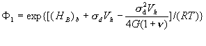
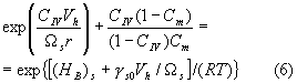
![]() (3a)
(3a)
![]() (3b)
(3b)
here the equilibrium carbon concentrations at
zones III and V have forms
![]() (4)
(4)
where
![]() (5)
(5)
where F2 = exp[(HB)s/(RT)], Cm is the bulk
carbon concentration, Vh is the molar volume of carbon, R is the gas constant, 1/Wi is the carbon coverage at interfaces, ![]() and
and ![]() are the critical values of carbon concentration at zone III,
required for slow and fast fracture, respectively, g0 is the ideal work of intergranular
fracture in the absence of carbon, and
are the critical values of carbon concentration at zone III,
required for slow and fast fracture, respectively, g0 is the ideal work of intergranular
fracture in the absence of carbon, and ![]() is the chemical potential difference between the crack
surface and the stressed grain boundary. The equations for constant carbon
concentrations also can be found at zones I and IV. By this, CI coincides with CV, in which (HB)s is replaced
by (HB)b, and
for CIV we have equation
is the chemical potential difference between the crack
surface and the stressed grain boundary. The equations for constant carbon
concentrations also can be found at zones I and IV. By this, CI coincides with CV, in which (HB)s is replaced
by (HB)b, and
for CIV we have equation
where r is
the curvature radius of the arc-shaped crack tip, and gs0 is the crack surface energy in the absence of
carbon. At the same time, due to the
variable stress distribution (1) the carbon content at zone II is not constant.
The relationship between the critical stress intensity required to propagate
the crack (for slow, fast or steady state fracture) and to change the ideal
work due to the carbon segregation is stated by using the local energy balance
condition as [21]
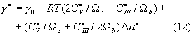
![]() (7)
(7)
where the superscript c corresponds to certain fracture state, Kd is the local
stress intensity factor, connected with the dislocation free zone size ahead of
the crack tip (d) and local stress (sd) in
this zone by the equation approximately derived from the load balance condition
between a crack with a linear stress intensity and that with local stress [21]:
pd = (Kd /sd)2.
Moreover, a relation between sd, Kd and dc follows from the condition, that the
elastic energy release rate is the same as the J integral, i.e.![]() . Then the threshold apparent stress intensity,
. Then the threshold apparent stress intensity, ![]() , is given by the relationships (1b) and (7)
, is given by the relationships (1b) and (7)
![]() (8)
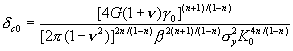
(8)
where K0
is the fracture toughness, ![]() is the critical crack
opening displacement (CCOD) required for various fracture processes
(superscript c), and dc0 is the
CCOD in the absence of carbon, defined as
is the critical crack
opening displacement (CCOD) required for various fracture processes
(superscript c), and dc0 is the
CCOD in the absence of carbon, defined as
Note, that in order to the crack to maintain
the dislocation free zone during the growth, besides the inequality (7), it is
necessary to satisfy additional condition, namely the total energy balance
criterion in the form [21]
![]()
where gp is the plastic work due to the
generation and motion of screening dislocations, which could be found
numerically, e.g. in the case of a linear dislocation array.
2.2. Steady state crack growth
Assume that the carbon diffusion along stressed
boundaries and crack surfaces is the mechanism, which controls the intergranular
embrittlement and affects the crack growth rate. By this, the bulk diffusion
effects on CIIC are neglected. Under the geometrical and loading conditions of
above considered equilibrium crack growth problem, the steady state case
indicates subcritical intergranular crack growth with constant velocity. Taking
into account the grain boundary and crack surface zones (II-V) the fluxes of
carbon in these regions, ![]() , can be stated as
, can be stated as
![]() (10)
(10)
where Di
is the diffusivity of carbon,
![]() is the carbon
concentration, i is the subscript
indicating b or s, and j is the
superscript indicating various interface zones,
is the carbon
concentration, i is the subscript
indicating b or s, and j is the
superscript indicating various interface zones, ![]() are the corresponding
chemical potentials. The differentiation with respect to s is carried out only at zone IV, by this, s is the variable arc length at the correspondent part of the
arc-shaped crack tip. The continuity equation of fluxes is
are the corresponding
chemical potentials. The differentiation with respect to s is carried out only at zone IV, by this, s is the variable arc length at the correspondent part of the
arc-shaped crack tip. The continuity equation of fluxes is
![]() (11)
(11)
where t is
the time. Based on equations. (1), (10) and (11), and also the relationships
between the interface energies, ![]() , and the amounts of carbon,
, and the amounts of carbon, ![]() , in the various zones, derived from the Gibbs theory and
dilute solute approximation as
, in the various zones, derived from the Gibbs theory and
dilute solute approximation as ![]() , the second-order differential equations, controlling the
carbon diffusion in the intergranular cracking regions, can be obtained,
analogously to [25]. It is assumed, the steady state crack growth maintains the
equilibrium values at the crack center and at the triple point of grain
boundaries ahead of the crack. It should be noted the present boundary
condition is a first order approximation because the equilibrium content of carbon
at the triple grain junction is difficult to attain, especially at sufficiently
high velocity of crack. The interface conditions find, that the chemical
potentials and fluxes of carbon must be the same at each interface in order to
maintain the continuity of the carbon flux. So, it is stated the boundary value
problem for solution of which some relationships defined in the equilibrium
crack growth to be used, namely: the local equilibrium condition at the crack
tip, the geometrical crack tip conditions, and also the crack tip condition
derived from the local energy criterion (7). The carbon diffusivity effect is
determined by the ideal work of steady state fracture
, the second-order differential equations, controlling the
carbon diffusion in the intergranular cracking regions, can be obtained,
analogously to [25]. It is assumed, the steady state crack growth maintains the
equilibrium values at the crack center and at the triple point of grain
boundaries ahead of the crack. It should be noted the present boundary
condition is a first order approximation because the equilibrium content of carbon
at the triple grain junction is difficult to attain, especially at sufficiently
high velocity of crack. The interface conditions find, that the chemical
potentials and fluxes of carbon must be the same at each interface in order to
maintain the continuity of the carbon flux. So, it is stated the boundary value
problem for solution of which some relationships defined in the equilibrium
crack growth to be used, namely: the local equilibrium condition at the crack
tip, the geometrical crack tip conditions, and also the crack tip condition
derived from the local energy criterion (7). The carbon diffusivity effect is
determined by the ideal work of steady state fracture
where
![]() ;
;
the superscript ![]() indicates the steady
state fracture. The boundary value problem can be solved numerically, e.g. by
using the Runge-Kutta method. The boundary conditions at the triple points
allow to study the effects of grain sizes on the kinetics of CIIC. Then, the
model of the steady state crack growth caused by the carbon segregation can be
added to previously developed modeling of the toughening mechanisms, acting
into HTSC systems [1, 14-18, 26]. At the same time, the size effects can not be
estimated in the cases of the equilibrium slow and fast cracks.
indicates the steady
state fracture. The boundary value problem can be solved numerically, e.g. by
using the Runge-Kutta method. The boundary conditions at the triple points
allow to study the effects of grain sizes on the kinetics of CIIC. Then, the
model of the steady state crack growth caused by the carbon segregation can be
added to previously developed modeling of the toughening mechanisms, acting
into HTSC systems [1, 14-18, 26]. At the same time, the size effects can not be
estimated in the cases of the equilibrium slow and fast cracks.
3. DISCUSSION
The
numerical results in the case of equilibrium crack growth obtained for
different values of the bulk carbon concentration, Cm, are presented in Table 1 (slow crack) and Table 2
(fast crack). Note that the spreads of values of the key material parameters
could be considerable in dependence on the manufacture techniques,
compositions, thermal and mechanical treatments, etc. Therefore, an optimum
selection should be realized by using the maps of material properties and
fracture features [1]. Nevertheless, in the present paper we are limit by
concrete set of parameters, only, namely:g0 = 1 J/m2,1/Wb = 1/Ws = 8.1*10-5 mol/m2,
(HB)s = 50KJ/mol, , (HB)b = 10 KJ/mol, n =
0.1, sy =
10MPa, Vh = 2*10-6 m3/mol, R = 8.316 J/mol K, n
= 0.2, K0 = 1MPa m1/2,
G = 50GPa, T = 1110K. By equating the right parts of the equations (1a) and
(1b) at the |x| = a+d and Ka = K0, and following consideration of the
relations (3a), (4), (5), and (7) for slow crack and (3b), (4), (5), and (7)
for fast crack the problem is reduced to numerical solution of transcendental
algebraic equations. These equations allow to state the relationships gc and
the critical tip conditions (![]() ) to Cm.
Then, the values of
) to Cm.
Then, the values of ![]() are determined from
equation (8) using the calculated values of gc and
are determined from
equation (8) using the calculated values of gc and ![]() . As it is shown by the numerical results, all auxiliary
parameters (
. As it is shown by the numerical results, all auxiliary
parameters (![]() )change monotonously with Cm
for both slow and fast fracture. In particular, the normalized
parameter, gc/g0, decreases with increase of Cm. At the same time, the
normalized parameter,
)change monotonously with Cm
for both slow and fast fracture. In particular, the normalized
parameter, gc/g0, decreases with increase of Cm. At the same time, the
normalized parameter, ![]() , increases together with Cm.
These alternative contributions into
, increases together with Cm.
These alternative contributions into ![]() cause its nonnmonotonous behavior in the dependence on Cm. By this, the
strengthening effect on
cause its nonnmonotonous behavior in the dependence on Cm. By this, the
strengthening effect on ![]() (i.e., when
(i.e., when ![]() > 1) occurs when the segregation of carbon in the crack
regions strongly affects the crack tip condition (i.e. reduction of
> 1) occurs when the segregation of carbon in the crack
regions strongly affects the crack tip condition (i.e. reduction of ![]() ) but it does not produce a substantial reduction in gc [see
equation (8)]. More evident change all auxiliary parameters in the case of slow
crack to compare with the fast crack at the considered range of Cm proposes the more
susceptibility of slow growth on CIIC increase. Then, it is apparent, that
under the condition of a dislocation-screened crack, the carbon segregation
induces slow fracture more readily than fast fracture. The weak change of
) but it does not produce a substantial reduction in gc [see
equation (8)]. More evident change all auxiliary parameters in the case of slow
crack to compare with the fast crack at the considered range of Cm proposes the more
susceptibility of slow growth on CIIC increase. Then, it is apparent, that
under the condition of a dislocation-screened crack, the carbon segregation
induces slow fracture more readily than fast fracture. The weak change of ![]() on Cm in both cases of slow and
fast cracks is apparently caused by small range of Cm (while this is real bulk carbon concentration into
HTSC systems). The presented numerical example should be specified with more
accurate selection of key parameters for certain HTSC.
on Cm in both cases of slow and
fast cracks is apparently caused by small range of Cm (while this is real bulk carbon concentration into
HTSC systems). The presented numerical example should be specified with more
accurate selection of key parameters for certain HTSC.
For
the used local energy criterion, which is controlled by CIIC, the dependence of
![]() on the ideal work of
fracture, the crack tip conditions and the plastic deformation properties [see
equation (8)] is somewhat similar to that obtained by Weertman [27]. The
difference consists in that the present paper explicitly includes not only the
embrittlement effect of carbon but also the crack tip conditions affected by
the carbon segregation. It should be noted, the presence of a
dislocation-screened crack and the microscopic behavior of plastic deformation
associated with CIIC have not yet been experimentally verified in HTSC
compositions. However, as it has been shown by Rice and Thomson [28] an
intergranular crack remains atomistically sharp when an energy barrier for the
nucleation of a dislocation loop at a crack tip is present. This barrier is
produced due to a low level of stress intensity at the crack tip in the
presence of screening dislocations stated by the dislocation sources (e.g.,
such as intergranular boundaries, particles, defects, etc.) [29]. Thus, the
relative strength of energy barriers for dislocation nucleation produced by the
crack tip or/and the other dislocation sources states whether a crack tip maintains
an atomistical sharpness or emits dislocation loops, Obviously, the carbon
segregation in HTSC causes a complex effect on the dislocation behavior. Then,
the occurrence of the dislocation-screened crack tips is possible in the
presence of carbon depending on how carbon affects the generation of
dislocation at the crack tips and the other dislocation sources. Besides the
crack tip conditions, the strength of carbon binding at crack surface and
intergranular boundaries also controls the carbon embrittlement of the grain
boundaries. It is known, that the value of (HB)s is much higher than that of
(HB)b, and they are found by the conditions at interfaces
such as solute or carbon coverage, structure and roughness. Moreover, a high
degree of lattice incoherence (e.g., at the interphase boundary [29]) can also
state a higher susceptibility to carbon embrittlement of HTSC. Obviously, there
are also another factors controlling the strength of carbon binding at
interfaces. So, the values of carbon binding need an accurate experimental
foundation for considered HTSC systems.
on the ideal work of
fracture, the crack tip conditions and the plastic deformation properties [see
equation (8)] is somewhat similar to that obtained by Weertman [27]. The
difference consists in that the present paper explicitly includes not only the
embrittlement effect of carbon but also the crack tip conditions affected by
the carbon segregation. It should be noted, the presence of a
dislocation-screened crack and the microscopic behavior of plastic deformation
associated with CIIC have not yet been experimentally verified in HTSC
compositions. However, as it has been shown by Rice and Thomson [28] an
intergranular crack remains atomistically sharp when an energy barrier for the
nucleation of a dislocation loop at a crack tip is present. This barrier is
produced due to a low level of stress intensity at the crack tip in the
presence of screening dislocations stated by the dislocation sources (e.g.,
such as intergranular boundaries, particles, defects, etc.) [29]. Thus, the
relative strength of energy barriers for dislocation nucleation produced by the
crack tip or/and the other dislocation sources states whether a crack tip maintains
an atomistical sharpness or emits dislocation loops, Obviously, the carbon
segregation in HTSC causes a complex effect on the dislocation behavior. Then,
the occurrence of the dislocation-screened crack tips is possible in the
presence of carbon depending on how carbon affects the generation of
dislocation at the crack tips and the other dislocation sources. Besides the
crack tip conditions, the strength of carbon binding at crack surface and
intergranular boundaries also controls the carbon embrittlement of the grain
boundaries. It is known, that the value of (HB)s is much higher than that of
(HB)b, and they are found by the conditions at interfaces
such as solute or carbon coverage, structure and roughness. Moreover, a high
degree of lattice incoherence (e.g., at the interphase boundary [29]) can also
state a higher susceptibility to carbon embrittlement of HTSC. Obviously, there
are also another factors controlling the strength of carbon binding at
interfaces. So, the values of carbon binding need an accurate experimental
foundation for considered HTSC systems.
The
detailed analysis of numerical results for steady state crack outruns of the
present paper. Note, only, the parameters corresponding to obtained ones for
slow and fast cracks are found in dependence on the crack velocity and the
carbon diffusivities at grain boundaries and crack surfaces. In particular, the
numerical results obtained for steady state crack indicate that the crack
growth rate is higher for smaller grain size, i.e. as the grain size decreases
the susceptibility to CIIC increases. In total, the solutions and numerical
results obtained in the paper can be used in the finite element formulations
and other numerical codes by which the stress-strain states distributions, kinetics
and parameters of intergranular defects during HTSC bulk manufacture can be
predicted.
Acknowledgements: This
work was supported by the Russian
Department of Education
(Program of Basic Researches in the Natural Science). I.A.P. thank the COBASE
Grant Program for financial support.
REFERENCES
1.
I. A.
Parinov, J. Composite Mechanics and Design 6
(2000), 445.
2.
W. Lo
et al., J. Mater. Sci. 30
(1995), 3995.
3.
W. Lo
et al., J. Mater. Res. 11 (1996), 786.
4.
S.
Sengupta et al., IEEE Trans. Appl.
Supercond. 7 (1997), 1727.
5.
Y. Gao
et al., J. Mater. Res. 5 (1990), 1363.
6.
G.
Selvaduray et al., J. Mater. Res. 7 (1992), 283.
7.
T. M.
Shaw et al., J. Mater. Res. 5 (1990), 1176.
8.
M.
Vallet-Reji et al., Physica C 230 (1994), 407.
9.
W.
Zhang and E. E. Hellstrom, Physica C 234 (1994), 137.
10.
J.
Wang et al., Supercond. Sci. Technol. 9 (1996), 69.
11.
Y.
Yamada, B. Obst, and R. Flukiger, Supercond. Sci. Technol. 4 (1991), 165.
12.
W.
Zhang et al., Adv. Cryog. Eng. 44B (1998), 509.
13.
I. A.
Parinov, Cryogenics 32 (1992), 448.
14.
I. A.
Parinov and L. V. Parinova, Supercond.:
Phys., Chem., Technol. 7 (1994),
79.
15.
I. A.
Parinov, E. V. Rozhkov and C. E. Vassil'chenko, IEEE Trans. Appl. Supercond. 7 (1997), 1941.
16.
I. A.
Parinov, E. V. Rozhkov and C.
E. Vassil'chenko, Adv. Cryog. Eng.
44B (1998), 639.
17.
Y. A.
Kozinkina and I. A. Parinov, Adv. Cryog.
Eng. 44B (1998), 449.
18. I. A. Parinov, Int. J. Supercond: Res.
Develop. 9-10 (1998), 16.
19. I. A. Parinov and E. V.
Rozhkov, IEEE Trans. Appl.
Supercond. 9
(1999), 2058.
20.
J. R.
Rice, Fracture. An Advanced Treatise.
Mathematical Fundamentals (edited by H. Liebowitz), Vol. 2, p. 204,
Academic Press, New York (1968).
21.
J.
Kameda, Acta Metall. 34 (1986), 867.
22.
M. P.
Seah, Proc. R. Soc. Lond. A349 (1976), 539.
23.
J. P.
Hirth and J. R. Rice, Metall. Trans. A 11A (1980), 1501.
24.
G. R.
Irwin, Appl. Mater. Res. 3 (1964), 65.
25.
J.
Kameda, Acta Metall. 34 (1986), 883.
26.
I. A.
Parinov, IEEE Trans. Appl. Supercond. 9 (1999), 4304.
27.
J.
Weertman, Acta Metall. 26 (1978), 1731.
28.
J. R.
Rice and R. Thomson, Phil. Mag. 29 (1974), 73.
29.
D. A.
Lisachenko, Supercond.: Phys., Chem.,
Technol. 6 (1993), 1757.